So, as I mentioned in my previous post, the power feed gearbox on the table had a loose ring inside it and it wasn’t immediately obvious which end of the input shaft this was supposed to be on. Further, the ring had become damaged after multiple impacts with one of the gears and thus needed to be replaced anyway.
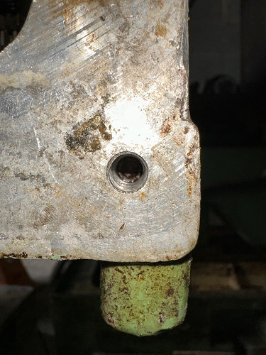
I have a manual for the machine now, but it leaves a lot to be desired and it’s mention of the gearbox is confined to a small section about installation and one diagram which is frankly worse than useless. Regardless, I needed to remove the motor to remove the input shaft, and so I set about figuring out how to do that. Firstly, there are no bolts going from the motor housing into the gearbox housing, and no bolts going from the gearbox housing into the motor housing. All there is is just this one bolt under the gearbox outer cover which points in the direction of the motor:

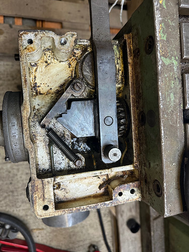
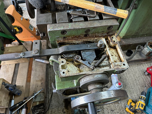
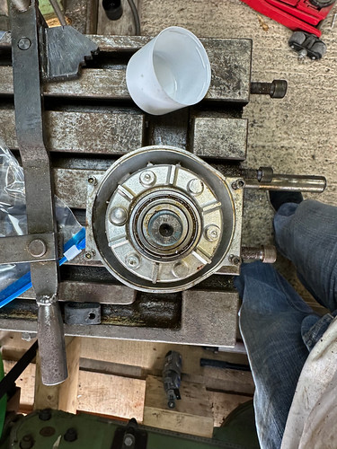
I also removed the top cover to check there was nothing there and gave it a little clean whilst I was there:

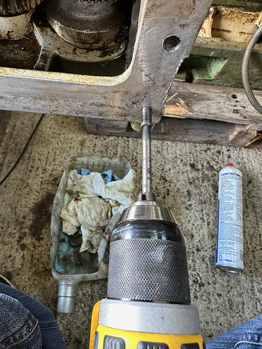
So, with that bolt under the cover being the only obvious retention method, I set about trying to remove it. It became obvious at this point that somebody previously has been here as the bolt head was completely rounded off! I tried hammering a Torx bit into it but that just turned as well, and a stud extractor did much the same. It was at this point I resigned myself to drilling it out, and spent the next 45 minutes or so working on drilling it out. Even when I’d measured and double measured the distance I’d drilled, the motor housing would still not move. I could rock it back and forth rotationally, but as for movement outwards there was nothing.
After a couple of hours of this and multiple opinions from other people, we decided to just try and whack it out, come what may. There was no obvious other fixing, there was no other retention, and it had to come out. I used an old jack handle as a drift and hammered it, but it still didn’t really want to move. We applied some leverage and unfortunately the casting gave way:


Bugger.
At least the shaft moves back and forth now. At this point I realised that the wheel was jammed against the gear again, and the shaft wouldn’t move back with the wheel in place. If I had been thinking straight at this point I probably would’ve stopped and re-assessed the whole situation, but just wanting the damn thing out I took a dremel to the edge of the wheel to make it clear the gear. This isn’t terrible as it was already damaged and I need to make a new one anyway.

Of course, at this point the other half of the casting is still stuck in the gearbox. Being able to look at it head on meant that it became clear that the top retaining bolt that I had drilled out was actually partially still holding the ring in place as it was at an angle and the drill bit hadn’t quite managed to take the furthest edge. I tried to drill out the rest, however at this point the drill bit snapped in the hole. This necessitated drilling out a piece of the aluminium mounting casting to get purchase and extract the drill bit, which happily came out without too much hassle.
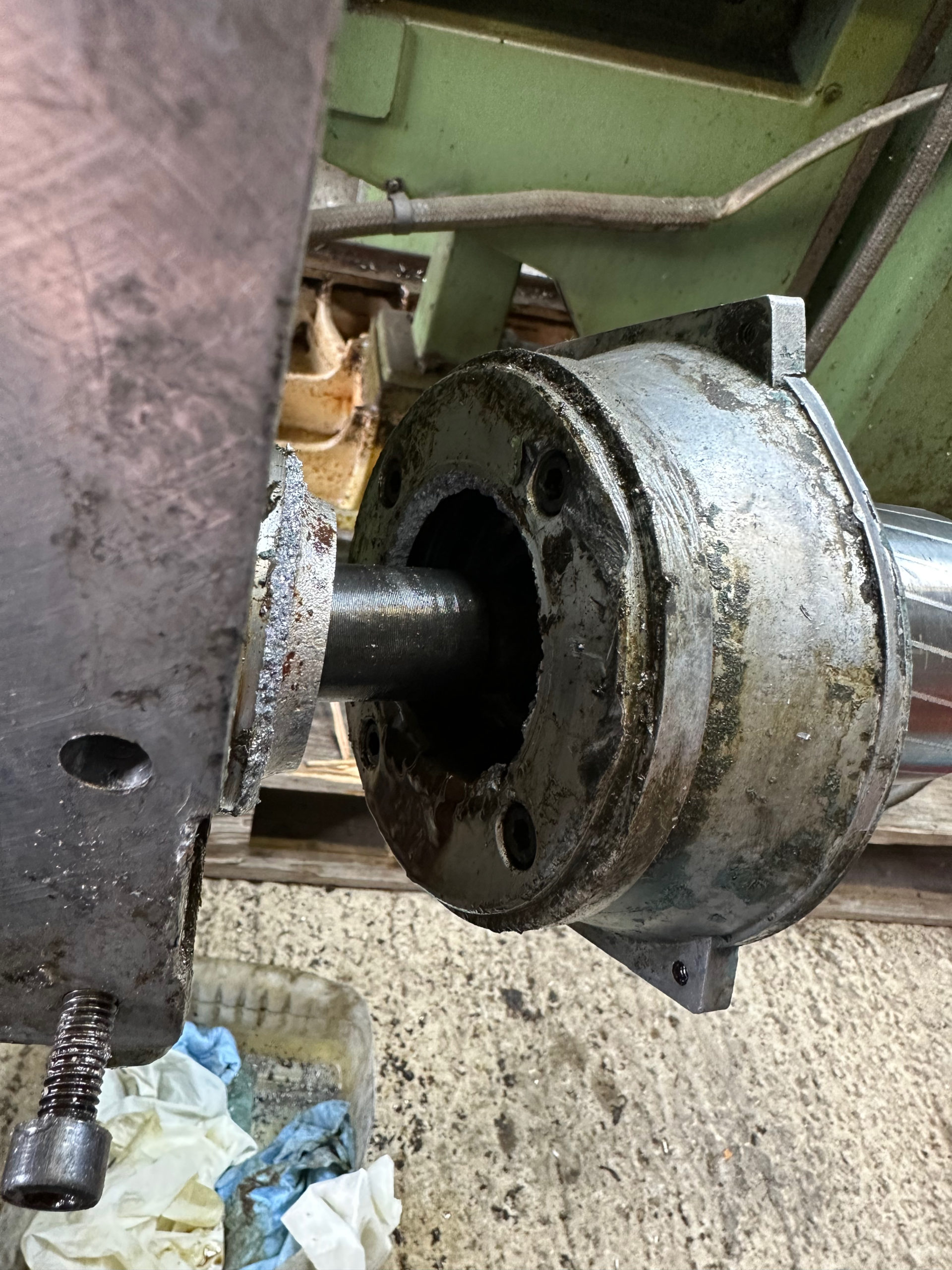
I managed with some brute force and ignorance to hammer out the rest of the mounting ring, and with it the shaft came free.


With it out, it became clear that there was in fact a second fixing method. The bottom of the ring is held in place by another bolt, but where could this be accessed from?

Well, it turns out that behind one of the case cover mounting bolts is another bolt. Again, with a tiny allen key head that had been partially rounded off.
It also didn’t help that whomever had re-fitted the gearbox cover plate last time had used silicon sealant and had put enough on that it had gone down the bolt hole and made it impossible to access the head. Once this was extracted I could focus on getting the bolt out:
This time the stud extractor worked, but that bolt is damaged and the last person that was here really knackered the head.
So, now with a broken casting and the retaining fixtures out of the way, I headed home to figure out how to make a new one. I initially considered just having a friend TIG weld it back together so I could true it up on the lathe and re-use it, but the damage to it is fairly significant and not being an incredibly complex part this seemed like a short cut way of doing it. I then thought I’d turn a new one up out of 6″ bar stock, but I don’t have any and it seems the prices have shot through the roof, so I didn’t fancy machining 80% of a bar away at £70 a go.
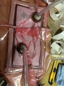
Regardless, I drew it up in CAD and 3d printed a prototype:

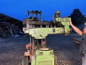
I took this up the next day and sure enough it fit so I know the drawing is good. This got me thinking about how to better retain the motor as even though I will helicoil the hole I drilled out, and I will also fit a longer lower casing bolt to utilise the bottom retainer, I don’t like this method and think it leaves margin for error. In order to necessitate better access to the gearbox I decided to remove it from the machine, something I wish I had done the day prior:


Luckily it came off without too much of a fight:


I then noticed that the motor end housing that had come off the day prior with half of the casting also hadn’t survived the removal session unscathed, as it is ever so slightly bent with a tiny crack on one side:

Really not ideal, and a lesson in why to sit back and properly consider things in future.
So, there are several things that I now need to do:
- Re-design the motor mount to better hold the motor
- Make a new motor mount
- Helicoil the drilled out gearbox hole
- Repair or replace the motor end housing (or the whole motor if it comes to it)
Sigh.
So, I gave it some thought and decided that the best course of action was to improve the mount by adding bolts from the outside that directly connect it to the gearbox. For this, I’m going to need to drill and tap two holes in the gearbox casing but I think this should be fairly simple (hopefully!). I measured up the supporting ribbing inside the gearbox and made notes of where it is so my holes could avoid it. I then went home and drew up & prototyped some parts:


The way this works is the extended circle around the mount offers an addition edge on which to mount a bolting block that can then be attached by threaded bolts to the ring & to the gearbox housing.


So, how am I going to make all of this? The next post will tell all…