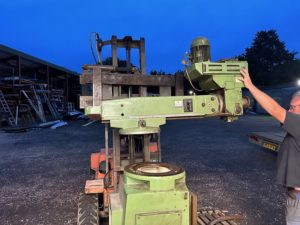
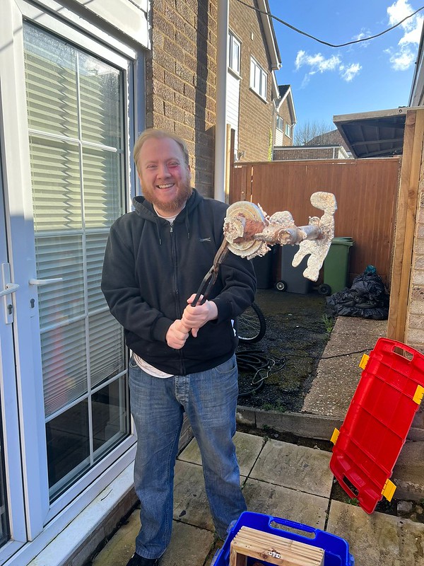
So, with the milling machine in place in the workshop, it was time to turn my attention back to the power feed gearbox motor mount that I unceremoniously broke back in October. I had designed a replacement with a new mount system and 3D printed a prototype back then, but now it was time to actually make one. Onwards!
So, with the requirement to make a new motor mount for the power slide and the pretty high cost of aluminium bar stock these days, I decided it was of course sensible to dive deep into a new rabbit hole of metal casting!
I’ve wanted to cast my own parts for a while now, but never had a good enough excuse to make the investment of time & money in my own mini-foundry, then this came along and it seemed like the perfect excuse!
First things first, I went on eBay and ordered a Vevor 12kg Propane Melting Furnace kit which comes with a 12kg graphite crucible, stainless steel furnace shell, ceramic insulating material, a bag of refractory cement, some tongs, and dual propane burners. This isn’t the be all and end all of furnaces by any means, but it’s a great starting place and I only paid £124 for the kit including shipping. I then went and bought some proper crucible tongs as the ones included don’t look fantastic. I got a set of lifting tongs and a set of pouring tongs on eBay as well, and they cost £60.
With tooling out of the way, I had to look to the consumable areas of smelting. Firstly, I needed sand. Not just any sand will do, and there are various types of sand which can be used for casting. “Green sand” is what is traditionally used, and this is made of a mixture of sand, clay, and water. Depending upon what grade of sand you use depends on what quality of surface finish you get. You can also go down a more professional route and use an oil based sand such as Bentomix, but this is very expensive (comparably) and only something I think I’ll look at once I’ve got the full hang of all of this. I ended up ordering 20kg of Bromsgrove Greensand from Artisan Foundry Store.
The next thing I needed was a parting agent. A lot of backyard foundries seem to use talc, but apparently this can cause a poor surface on the casting. I did some research and settled on Calcium Carbonate as apparently this is an excellent release agent and doesn’t affect the surface of the casting. Originally I was only going to order 1 – 5kg’s of the stuff, but it turns out that 5kg is as expensive as 25kg! So of course I ordered 25kg off of eBay. I also needed a special thin mesh bag to sprinkle it with, which I also ordered off of Artisan Foundry Store.
With all of that ordered, there were three more things I needed to do before I could get going:
- Make the parts from which to make the casting
- Make the moulding flask
- Buy propane
I decided to start out by modifying the models for casting. The original drawings were to use as prototypes, but in order to cast these ready for machining I needed to make some modifications.
First, I removed all of the holes & centre bore, and added some 4.2mm holes in which I could embed brass threaded collars:

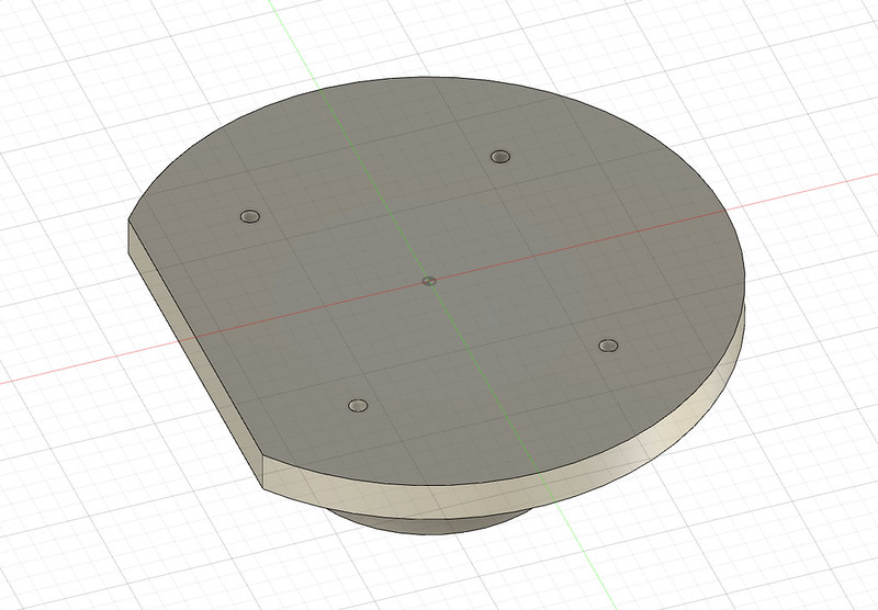


I additionally enlarged the parts by 2-3mm on all planes such that there was space to machine the surfaces on the lathe. Then I printed them:

Once they were done printing 14 hours later, I embedded the small brass threaded collars using a soldering iron:

Then I screwed in the brass studs temporarily:

The brass holes/studs are there such that when the item is packed in sand it can have the studs screwed in and be pulled up, hopefully without disturbing the sand surface.
I then put it in the casting drag, and then applied a layer of calcium carbonate parting powder:

I then packed in some green sand:

I also obviously made the cope to match the drag with the sprue and vent hole but I of course forgot to photograph this.
I then cut up some scrap aluminium wall decorations and started the little Vevor furnace:


I kept feeding aluminium scrap in until I felt I had enough molten aluminium to make the pour:

Then I lifted out the crucible, scraped off the slag, and made the pour (along with some ingots for the extra):

Once it’d cooled down a bit I knocked out the sand and removed the casting!
It wasn’t the cleanest casting, but it also wasn’t the worst. There was some areas where sand had fallen in and this caused some surface defects, plus a couple of deep ones, but the majority of these would be machined out and the ones that wouldn’t were non-structural, so good enough for me!
I then chopped off the sprue, runner, and vent:

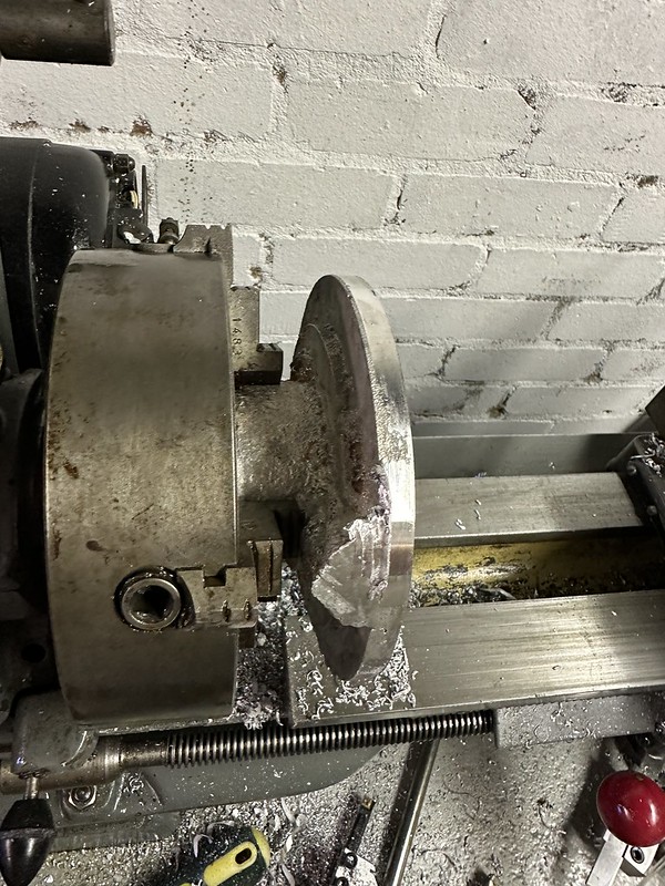
Popped it into the 4 jaw chuck on the little Myford ML7 and set about machining it. This alloy was quite difficult to machine well, it really didn’t want to play nice and no matter what speeds & feeds I used it, frankly, machined like crap with varying levels of hardness throughout. I guess that’s what you get for using a mix of scrap!


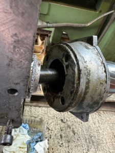
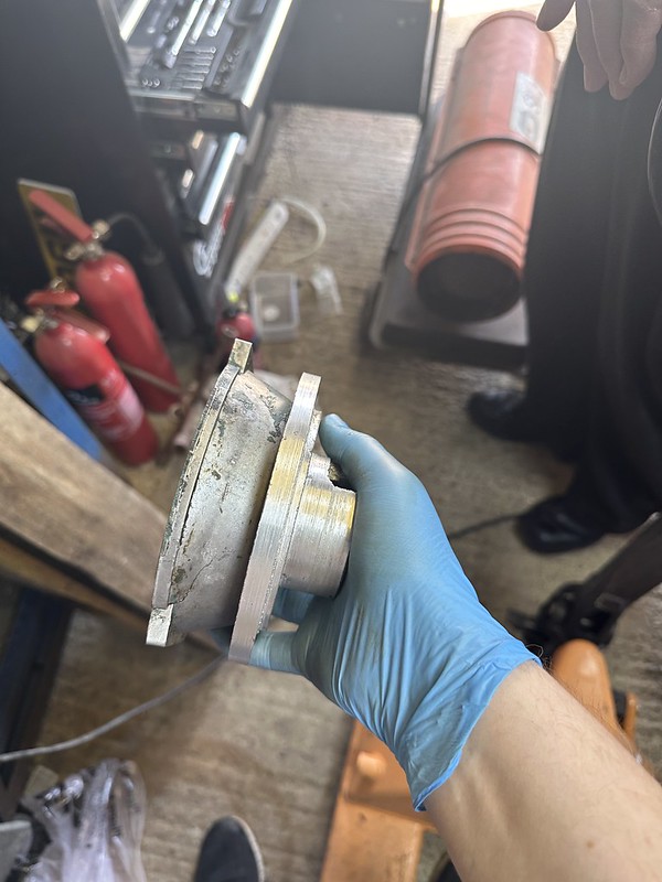
Testing it with the motor nose casing:
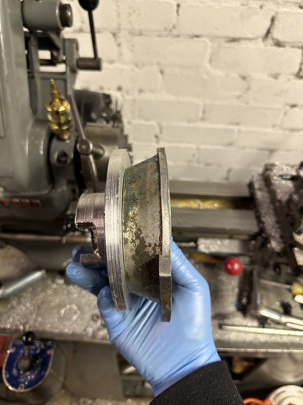
I fitted the shaft seal, but you can see some of the mild porosity/sand ingress in the casting in this photo. Still, it’ll do the job and I can’t be bothered to do it again for something nobody will ever see:

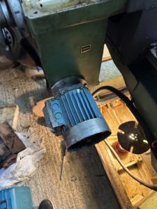
The motor nose casing was slightly bent so I re-shaped it, replaced the shaft seal, and bolted up the commutator:


I re-assembled the motor, but when power was applied from the mill controls the motor just vibrated and made a noise like an angry swarm of wasps in harmony. I figured there were two key possibilities: 1) The windings were shorted, or 2) A phase wasn’t working. I pulled the commutator out again and thoroughly cleaned the inside of the motor out with brake cleaner to remove any trace of the oil that had been in there that had previously leaked through from the gearbox. I then checked the windings with a multimeter and found them all to be in good order:

This suggested the issue was likely a phase not working, so I checked the fuses, and this one was blown:

I swapped one of the other ones in to test, and the motor (noisily!) span up! So that’s one problem down.
Now I know that the motor is good, I can drill the mount for the motor mounting holes. I didn’t want to do this if I was going to have to replace the motor, so now I know it works I can crack on!
I marked up the mount and used the pillar drill to drill the holes and the counter sinks for the bolt heads (this photo is the first two of the four):

and the motor nose bolted up perfectly:
and it fits up to the gearbox nicely!


I was then planning to drill the gearbox casing, tap it, and bolt the mount up using the extended ring, however I discovered the tap I thought I had for the bolts was the wrong thread pitch. I have however now borrowed one from my neighbour, so hopefully I can get this finished tomorrow (Easter Sunday)! I realised that my original idea of the extension piece might interfere with the motor nose, so I’m holding off on that one in the hope that this will be enough retention for the motor.